Introduction
I love going to music concerts. It’s my life! When I can’t make a concert, I do two things – try to stream it live through or find a recording online later. In both cases, the concert is no longer played back by instruments…it is played back by a speaker. We all know that listening to a live instrument never sounds like listening to the recording on speakers. No matter how high the quality of the speaker system, listening to recordings of concerts never sounds like the real concert. Why is this the case despite numerous advances in loudspeaker design and technology?
The problem
The reason is mainly due to dissimilarities in acoustical properties of an instrument and speaker. Consider a violin for instance. Briefly, a violin propagates sound in all directions and is thus able to fill a concert hall without amplification. A speaker by contrast is very directional. It sends sound out in one direction, this is why many speakers must be placed around a concert hall to fill a room of the same size. Moreover, the body of a violin radiates specific frequencies in specific directions. These frequencies in turn reflect on walls and ceilings before reaching the listener’s ears to form the “sound of a violin”. A speaker on the other hand directs all frequencies in one direction – straight at the listener. This means we lose the sound’s spatial information. Despite a speaker’s versatility in reproducing a range of frequencies, a speaker is unable to reproduce the spatial presence of these frequencies propagating from the instrument.
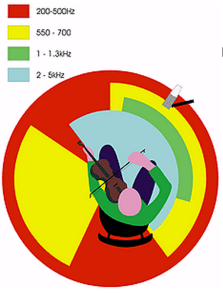
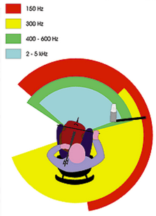
Radial patterns of various frequency bands for violin and cello. (Image from Sound on Sound)
The problem of spatial presence and directivity is complicated further by the recording technique employed. Let’s consider the industry standard microphone Shure SM57 for this discussion. All microphones exhibit a frequency response and naturally accentuate certain frequencies while attenuating others. No microphone has a flat frequency response – it’s a fact of life, well electrical engineering. Thus, the microphone employed will change the sound of the recorded instrument (I speak of it here as a “limitation” of physics, but in the world of audio engineering, a skilled engineer is one who is able to match the microphone response with recording task at hand).
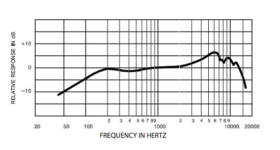
Frequency response curve for Shure SM57 (Image from Shure)
Moreover, professional studio microphones exhibit polar patterns. The sensitivity of the microphone changes according to the frequency – notice how the shape of the bell changes according to the frequency.
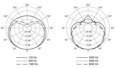
Polar pattern for Shure SM57 (Image from Shure)
Thus the microphone itself and its placement in relation to the instrument strongly affect the sound of the recorded instrument. The recording only captures the sound of the instrument at that one point in space. This recording is in turn played through a speaker system that also does not recreate the spatial behaviour of an instrument as discussed above.
To sum up
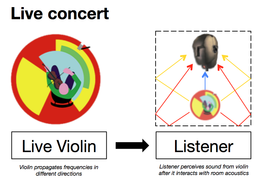
At a live venue, the instrument propagates sound in all directions. Different frequencies travel in different directions and these reflect off the walls of the venue before reaching the listener’s ear.
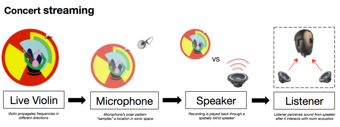
During concert streaming, a microphone records the instrument from one fixed location. The sound is played through a speaker, which as discussed before, does not propagate sound like an instrument. Note that sound from the speaker will emanate some sound from the sides (though not the back) and these waves reflect off the walls of the room and reach the listener’s ears. The main difference lies in how a real instrument propagates different frequencies in different directions. The speaker sends all frequencies in one direction, it will not discern high frequencies from low frequencies.
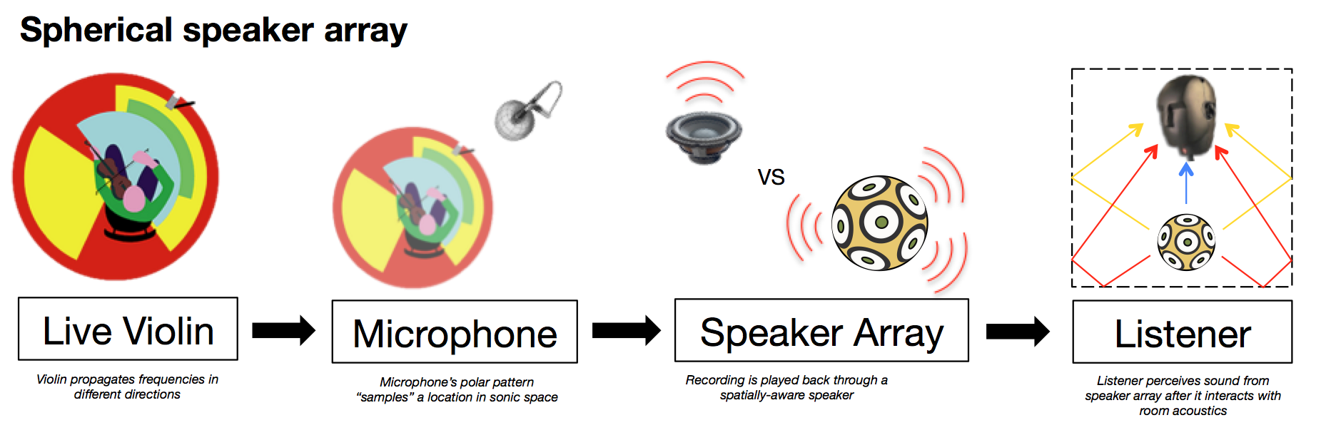
Researchers in the field of audio of spatialization at Princeton’s Sound Lab and UC Berkeley’s CNMAT have produced speaker arrays of various geometries to try and resolve this issue. Using multiple channels of audio, each speaker can individually propagate certain frequency bands in the correct direction.
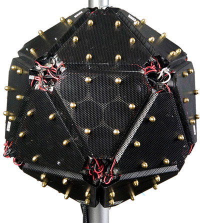
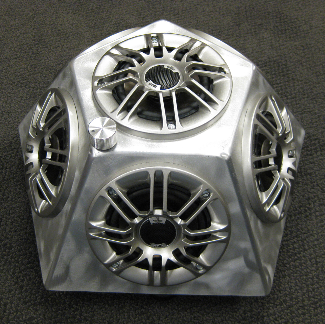
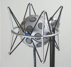
120-Channel spherical speaker from UC Berkeley’s CNMAT and 6-channel hemispherical speaker from Princeton.
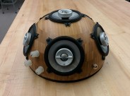
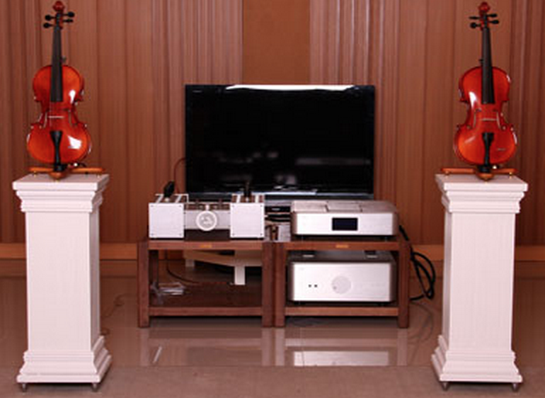
A hemispherical speaker I constructed to experiment with the above theories.
Although these speakers solve the problem of spatialized output, it still relies on a fixed microphone location. It’s like taking a photograph of a person from one angle and expecting the final picture to hold information of the back of the person’s head.
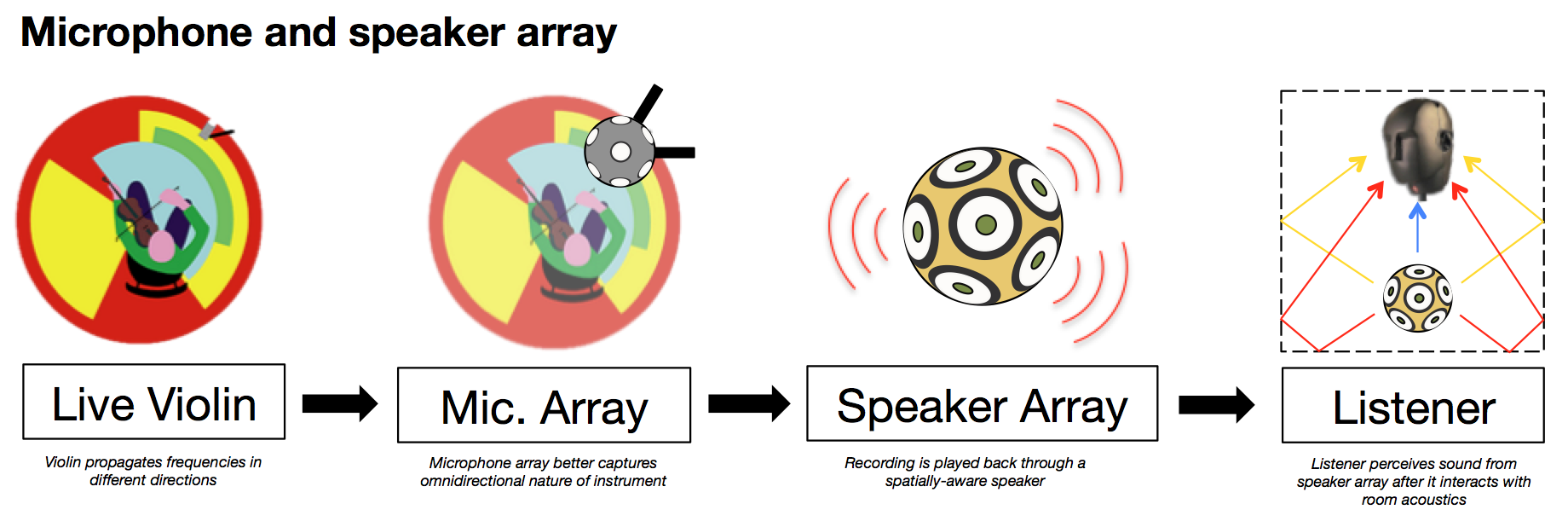
In the same way multiple speakers can be positioned into an array to produce spatialized output, multiple microphones can also be positioned in various geometries for spatialized input. When microphone arrays are used in tandem with speaker arrays, the spatial presence of an instrument can be recreated with greater accuracy compared to conventional recording playback techniques. These special sound systems can be found in acoustics labs at places like IRCAM in Paris, France.
The Idea
In order to transmit a live instrument from one concert to another, I propose we cut the microphones and speakers. Instead I’m interested in methods of transplanting the source vibrations of a live instrument to surrogate instrument to preserve all the associated acoustics. Stringed instruments like the violin and guitar produce their sound by amplifying the vibration string through a resonating body. In this project, I focus on the string family and in particular, the violin.
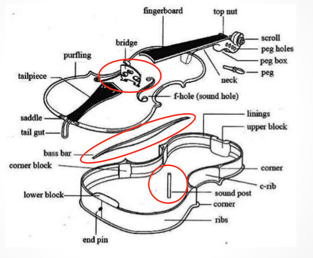
Violin Physics
We are very aware of the shape of a violin. What might not be as obvious are the components inside the violin, most notably the bass bar – which stiffens one side of the top plate and the sound post – which transfers the vibrations of the top plate down to the bottom plate. These will play vital roles when combined with the bridge of the instrument.
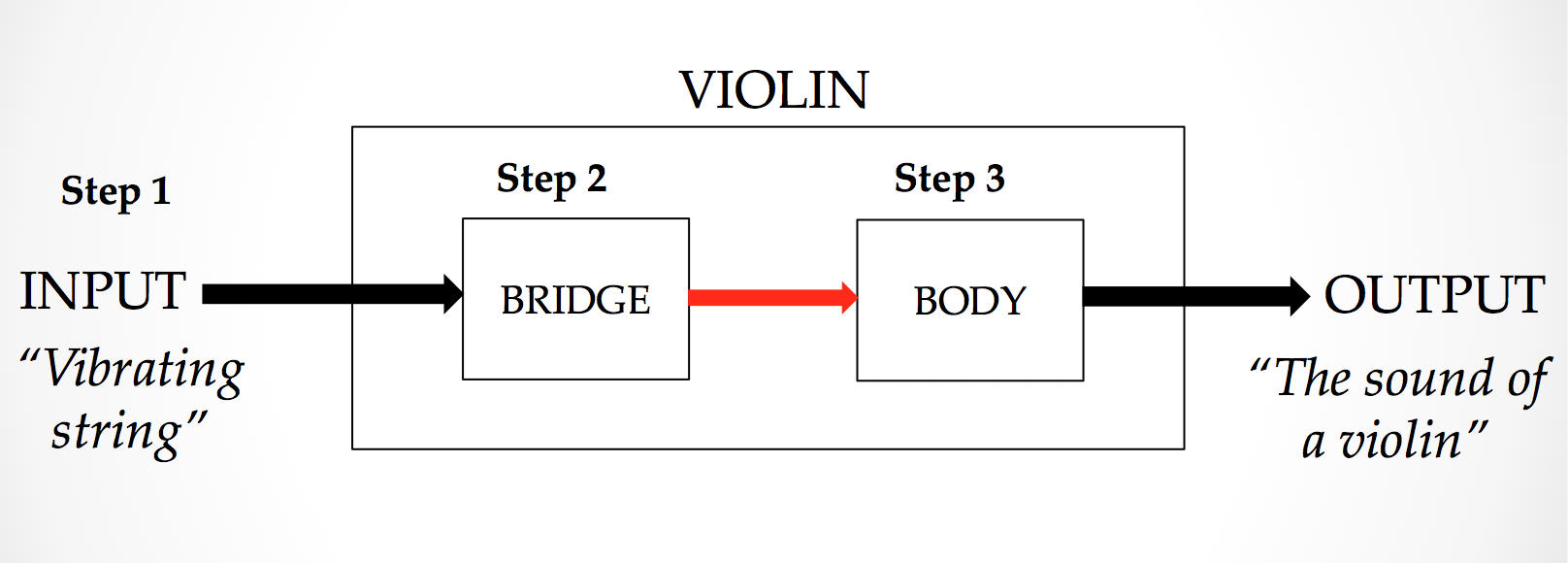
The violin as a system
We suggest the model of a violin as a system with an input and an output. There are 3 stages as to how a violin produces the “sound of a violin”. First, the string vibrates. Then, this causes the bridge to vibrate and the signal from the string to change. Next, the body also vibrates and the signal changes a second time to be heard as the “sound of the violin”. (There is a limitation to this model, which will be discussed later)
Step 1 – The Vibrating String
The plucked string is governed by the wave equation in one dimension. It is a sum of sinusoidal components in which higher partials decay relatively rapidly.
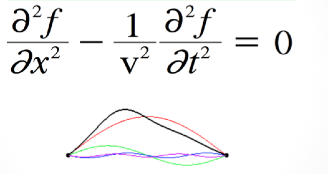
A great animation can be found using this link.
However, the bowed string is a completely different beast. What seems to the naked eye as a sinusoidal vibration is actually a “kink” that travels around the two boundaries. Helmholtz was the first person to observe this phenomenon and thus the kink is named as a “helmholtz kink”.
Check out this great animation and this awesome slow motion video.
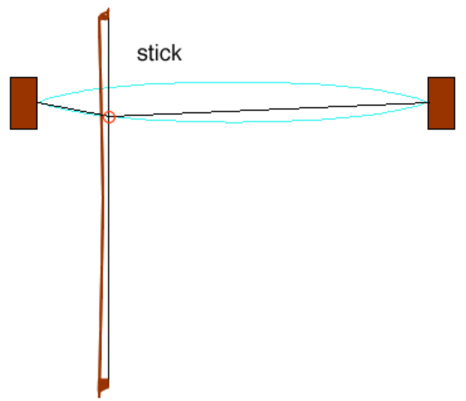
The motion is characterized by a “stick phase” where the bow’s friction moves the string up. Then the kink bounces back and snaps the string with a force greater than the bow’s friction. This puts the motion into a “slip phase” and the cycle continues. When the motion, speed and pressure of the bow is in sync with the traveling kink, a pleasant tone is produced! Novice violinists are unable to keep this two processes in sync and thus produce the squeaky tone that annoy the heck out of everybody.
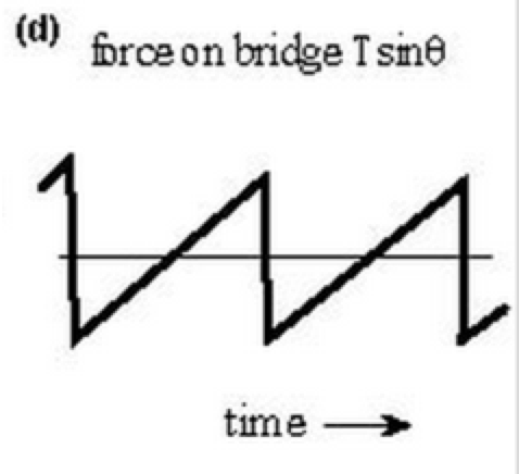
This movement causes a force on the bridge to vary according to a sawtooth wave, a type of wave that contains a lot of high harmonics. These higher harmonics are sustained by the constant force being applied by the bow. Contrast to a plucked string in which higher harmonics decay relatively rapidly.
This motion produces a force on the bridge which varies like a sawtooth wave.
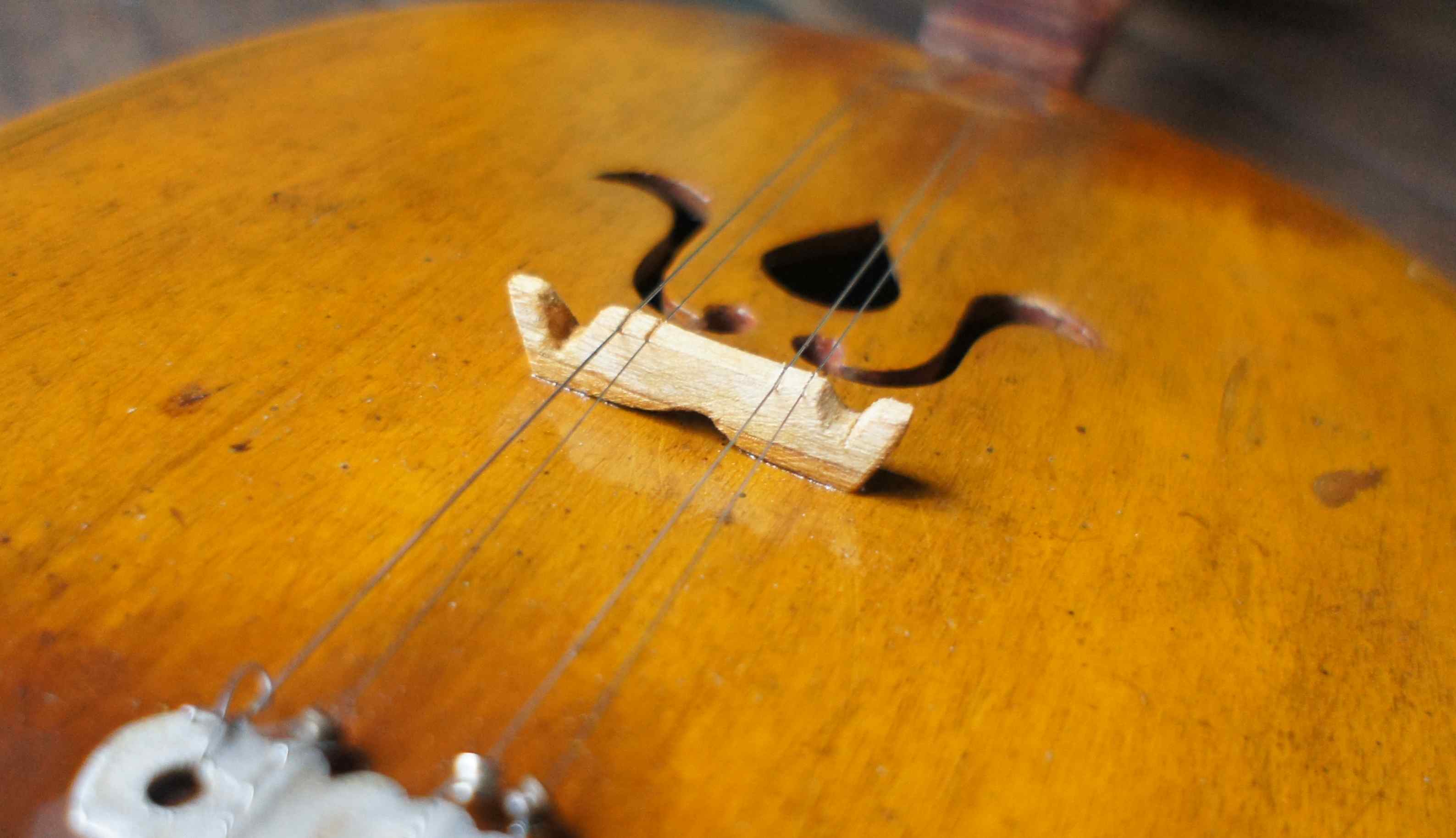
The Bridge
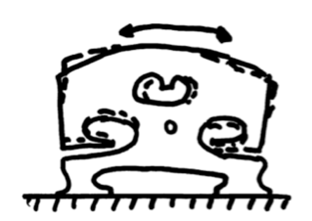
The purpose of the bridge is to change vibrations in the lateral plane from the strings to vibrations in the perpendicular plane (the plane in which the plates of the violin vibrate). The behaviour of the bridge is documented in great detail in L. Cremer’s “Physics of the Violin” (MIT Press 1981) and I will attempt to give a brief description here. One side of the bridge is restricted in motion by the presence of the bass bar directly underneath. When the string introduces a lateral force, the bridge almost “pivots” around this stationary foot. The free and vibrating foot thus moves up and down in the perpendicular plane and vibrates the top plate in the vertical plane. The sound post is placed directly below this vibrating foot to transfer vibrations to the bottom plate.
The second function of the bridge is also to act as a filter. E.V Jansson et al investigated in great detail the frequency response of the bridge and the effects of removing small amounts of wood from various locations on the bridge. Jansson et al identified key characteristics of the bridge – notably a strong resonance at 500 Hz and a “broad peak” region in between 2 – 3 kHz. Changing the geometry of the bridge shifts these peaks around.

This is where the behaviour of the bridge becomes more complicated. Cremer notes in his book that at lower frequencies, only one foot moves while at higher frequencies, the feet may move together or at different speeds. It is really quite remarkable how violin makers achieved this design ubiquitous to all string family instruments by trial and error. Apparently, they started out with a solid slab of wood and found through experimentation that sound transmits better when they carved out two feet. Interestingly, if one observes other simpler traditional instruments such as the Thai “Saloh” or fiddle, the small bridge is a small solid piece of wood. However, larger instruments like the Thai “Suhng” also have two legs.
The Body
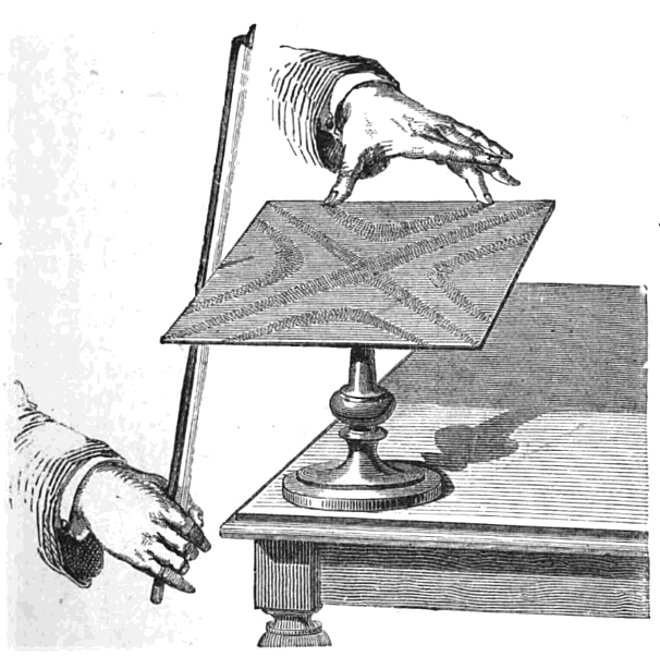
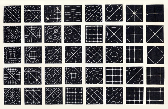
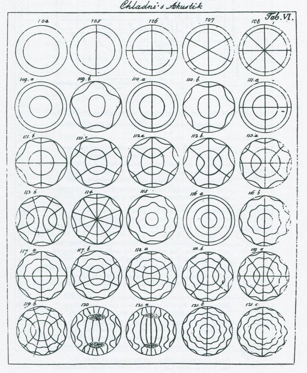
After the source signal is transformed by the bridge, it enters the body of the violin. The University of New South Wales has a great page on the frequency response of the body. These can be made visible using sand particles and Chladni patterns.
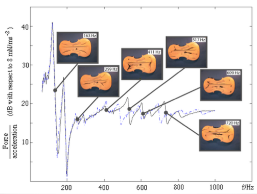
In the same way different vibrational modes cause resonances in 1D system like a string or a 2D system like a square or circular plateplate, the vibrational modes (or patterns) of the violin body give rise to its resonant peaks.
A detailed study of the violin body is beyond this paper and the reader is highly recommended to consult Cremer’s Physics of the Violin. Before we move on, it is also important to note the other modes of analysis used on the violin.
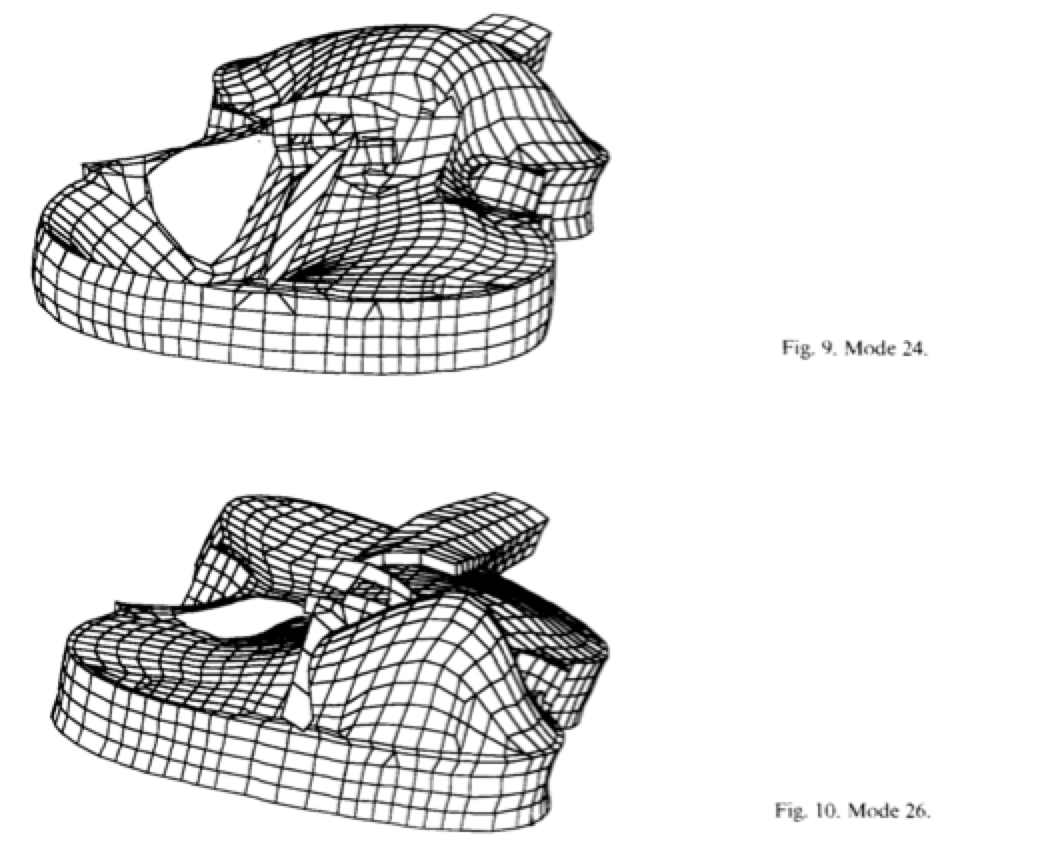
Interference holography reveals the systems of nodes and antinodes on the plate. A system of antinodes can be thought of like two point sources. At higher frequencies, the effects of constructive and destructive interference become more pronounced, explaining why directivity becomes more important the higher the frequency.

G Knott et al were the first to perform Finite Element Analysis to the body of the violin. The model produced results and frequency responses in agreement with the emperical findings.
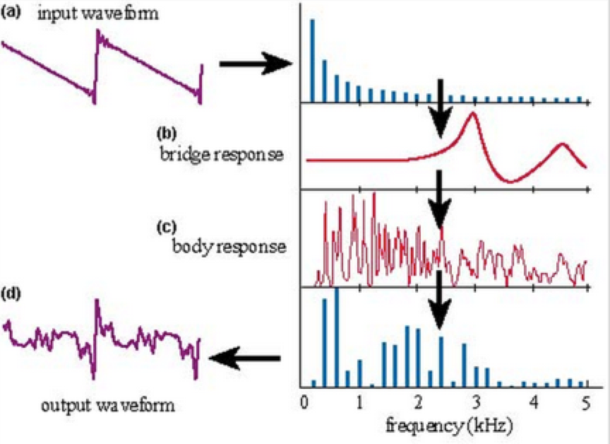
Violin Signal Flow
We can now appreciate the 3 steps behind how a violin produces its sound starting from the sawtooth generated by the string and the respective frequency responses of the bridge and body.
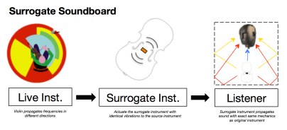
The surrogate soundboard
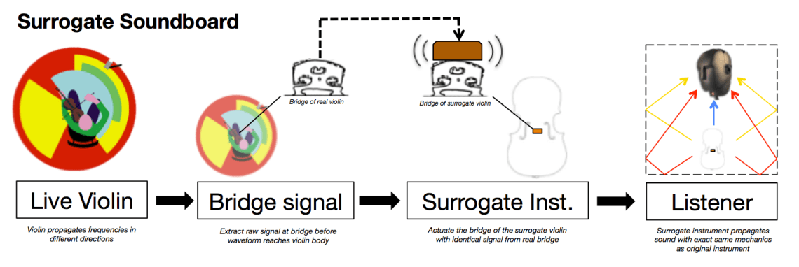
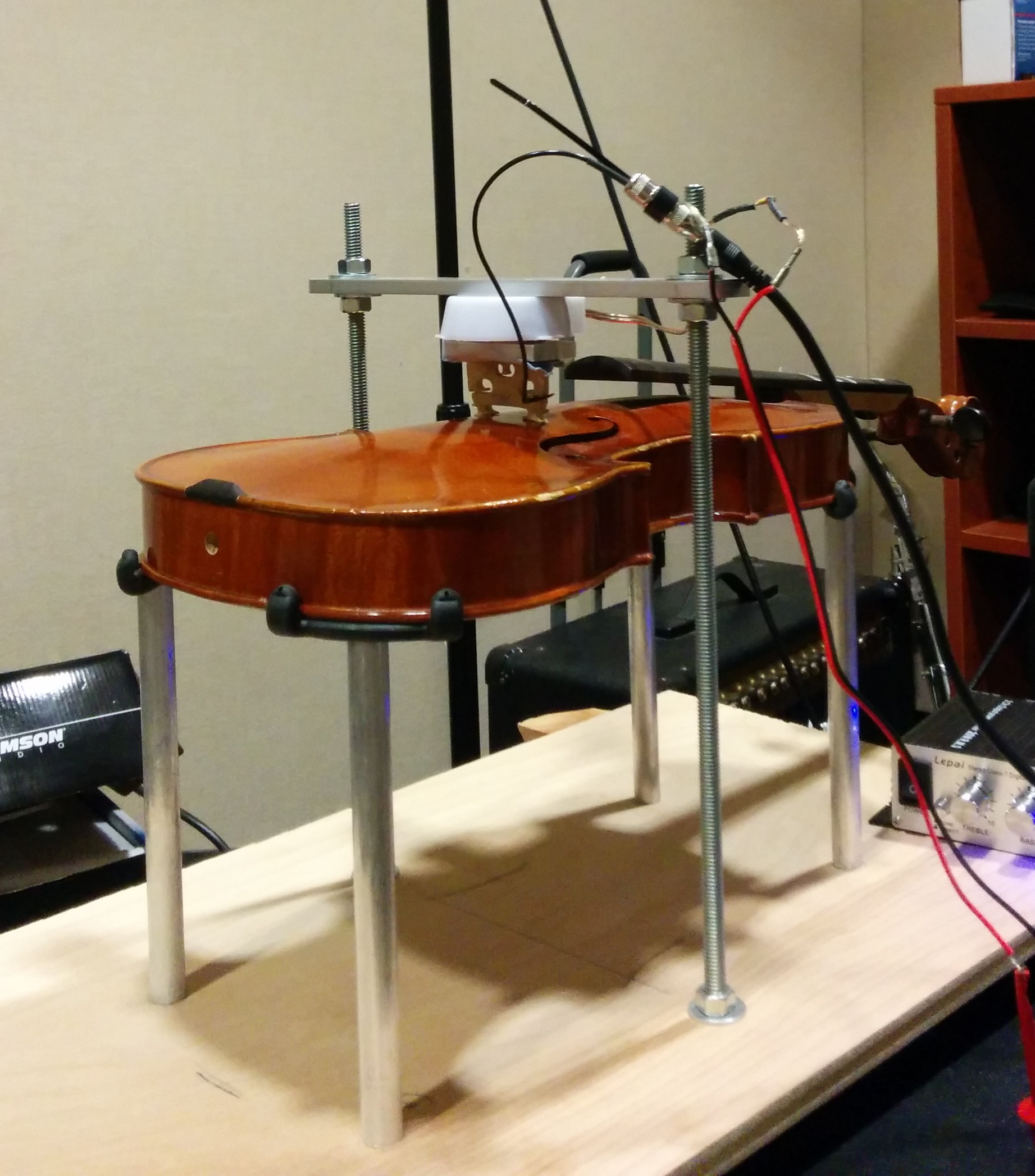
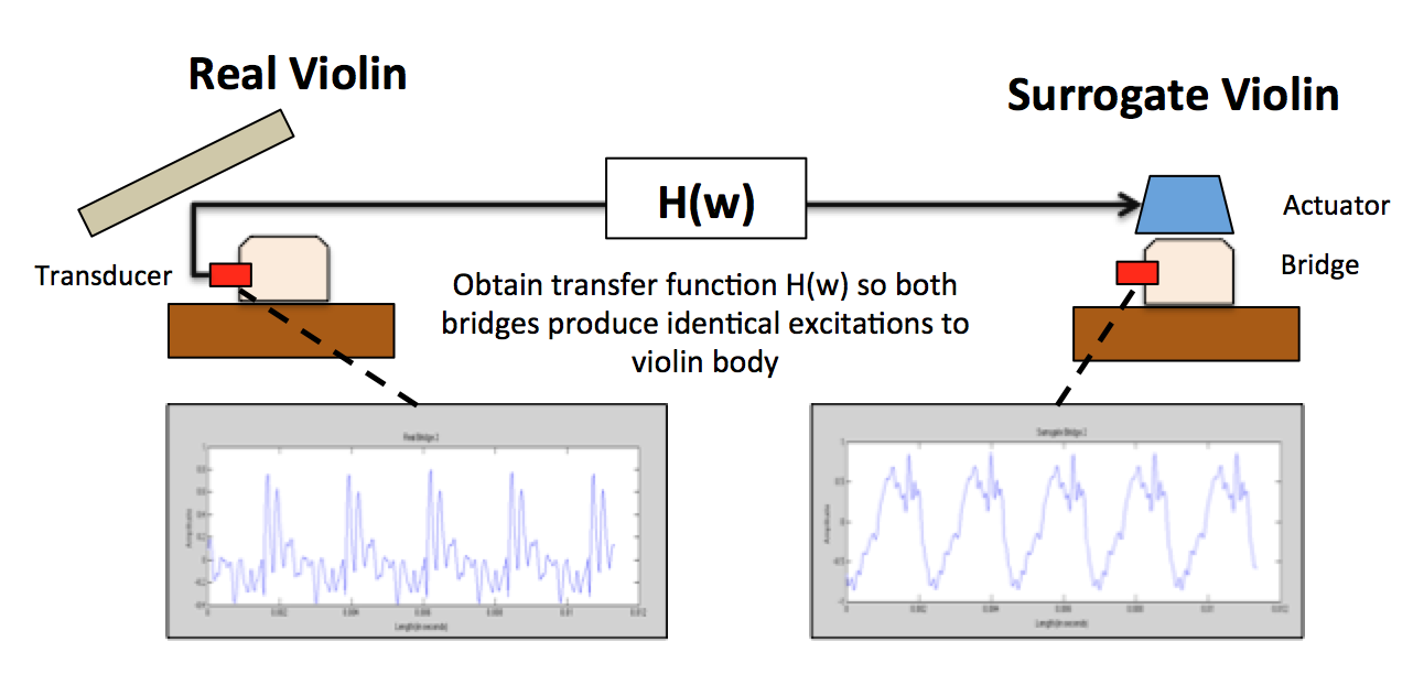
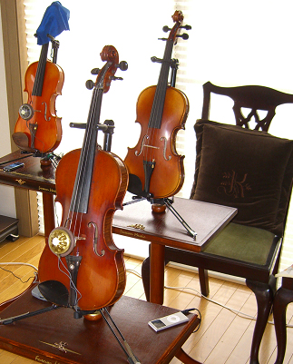
The surrogate soundboard attempts to preserve the original sound producing mechanics of the source instrument. We design an aluminium adapter that clamps onto the bridge and couples it with an actuator. This system suspended and held down by a bar to simulate the downward force of the strings. In this picture, the small transducer is used to measure vibrations from the bridge.

We obtain the signal from the bridge of a real violin. This is the signal before it hits the body of the instrument and is very “sawtooth-y” as expected. We send this signal to an actuated bridge on a surrogate violin and introduce the same vibrations on the surrogate soundboard as the original soundboard.
The sound on the surrogate soundboard however sounds like a violin! To the naked ear, the surrogate instrument behaves and sounds like the original instrument.
Preliminary results show that the signal at the bridge when measured at the same point is different from the original signal. This is expected because of the frame-actuator system introduced to the violin that has not been accounted for.
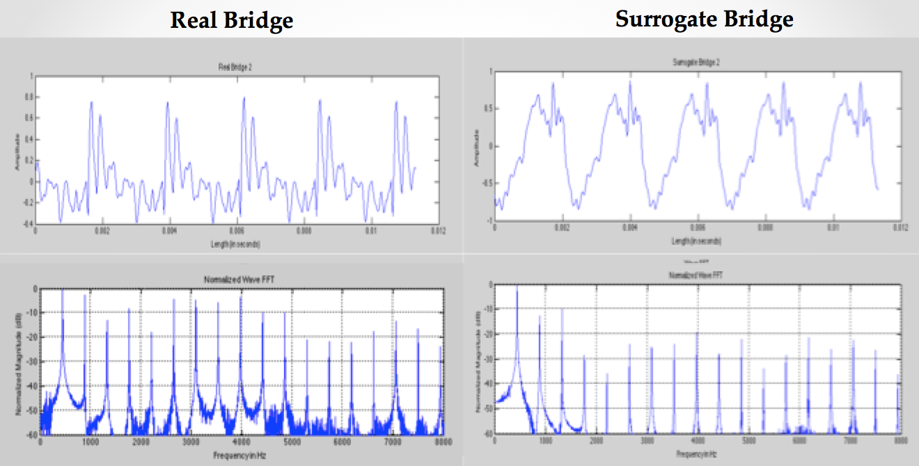
We are interested in finding a transfer function that transforms the signal in such a way that when the signal reaches the surrogate bridge, it produces the identical excitation on the surrogate body as the original instrument body.
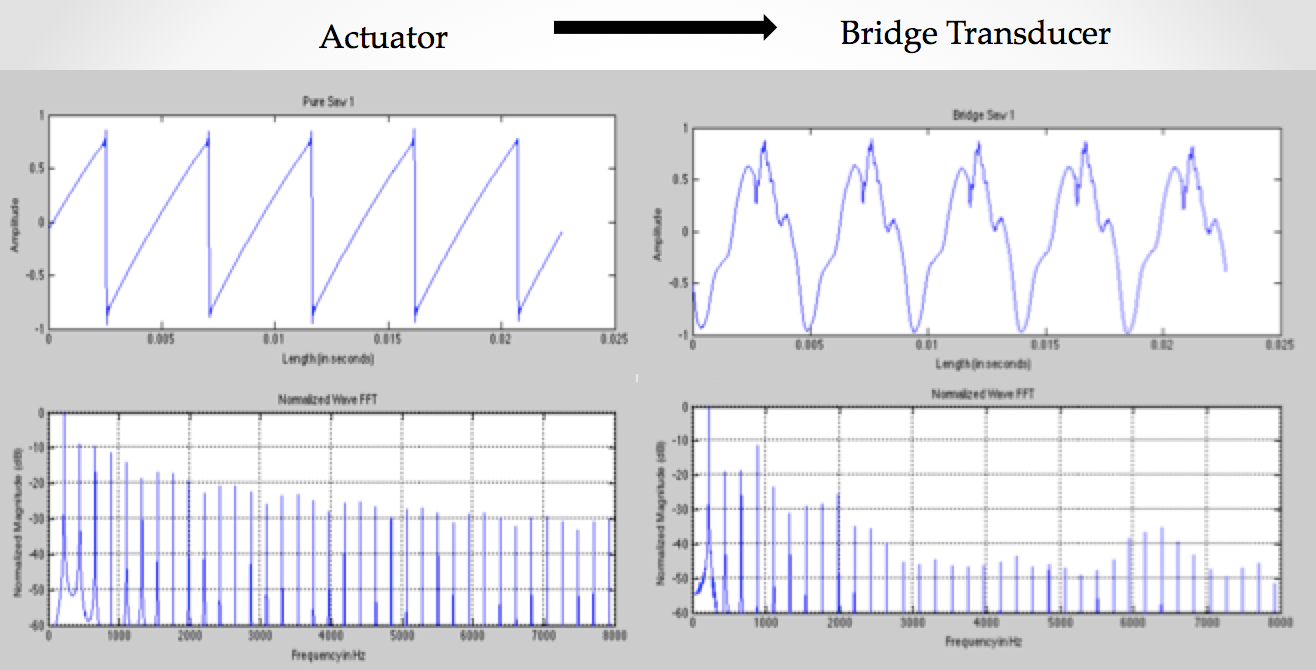
This will involve characterizing the system and analyzing its behavior to different input waveforms. For example, this is the transformation that occurs when a pure sawtooth wave is passed through the system.
The ideal surrogate violin
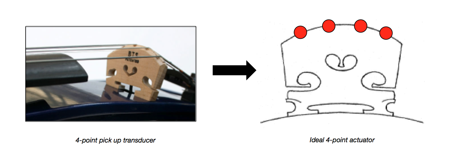
The ideal surrogate violin would use a 4-point transducer to pick up the signal of each individual string. These special bridges exist and are manufactured by a company called Barbera transducers.
The bridge of the surrogate violin would employ a 4-point actuator at the exact same spots where the strings are located. These micro-actuators will vibrate in the exact same way as the strings. However, no such infinitesimal actuator exists. Thus, we have adopted the bridge and string as a “lumped system”.
Applications
The surrogate soundboard can be used to:
Stream chamber groups to other surrogate chamber groups in other concert halls
- Stream entire orchestras across countries
- Allow one violinist to play multiple violins simultaneously
- Allow signal processing and other effects to be reproduced through the instrument body rather than a speaker
- Make instrumental lip-syncing a reality
- Sum multiple violin signals into one surrogate soundboard

Similar Systems
Note that the surrogate soundbaord does not attempt to recreate the “bowing motion” of a violin. Henry Sandell invented the self-playing violin in 1904 using a system of levers. Although a fascinating invention, it was extremely bulky, unable to match the nuances of human bowing and most importantly, will not reproduce the sound of a live violinist in real time. This project is motivated by the notion of live transmission between live violin and surrogate violin.
The Juno Violin Speaker uses the surface of the violin as the vibrating plate for a speaker by mounting actuators on the inside of the violin. It uses the same principle as putting an actuator on any surface and turning it into a speaker, might as well just stick the actuator on a cardboard box like in a previous project I did. It is designed to be a “regular speaker”, i.e it is optimized so that one can play Bob Marley and Eric Clapton from an iPhone through it.
The closest in design is a product made by a company called Forever R&D. The actuator clamps onto the bridge of any violin and introduces vibrations into the bridge of instrument. The system is designed to play regular mp3’s or Youtube videos through the violin. The system however, does not solve the problem of input. If you are going to actuate the bridge of the instrument, you need the signal from the bridge of the instrument, not the signal of the final instrument after it has gone through the various stages of wave transformation.
Various patents surrounding this issue also attempt to directly drive the plate of the violin or guitar with an actuator without regard to the bridge mechanics or try to solve the issue of pickup using a variety of creative methods.
Limitations
In its current form, the surrogate soundboard for violin does not account for the two feet of the bridge moving at different speeds. Since the entire bridge on the surrogate violin is being actuated by one source, both feet will move up and down with the same motion.
Assuming that the violin can be treated as three discrete signal components is valid only to a certain extent. In reality, the string-bridge-body system is a coupled system where motion in one component has an influence on the motion of other components. It is not like a traditional EE signal path where the amplifier k has nothing to do with the filter later down in the chain.
The surrogate soundboard aims to replace the strings with an actuator, it would be even better if the system was developed in a way that allowed it to “attach” onto any string violin.
These limitations will be addressed in the second iteration of the device in Fall 2014!
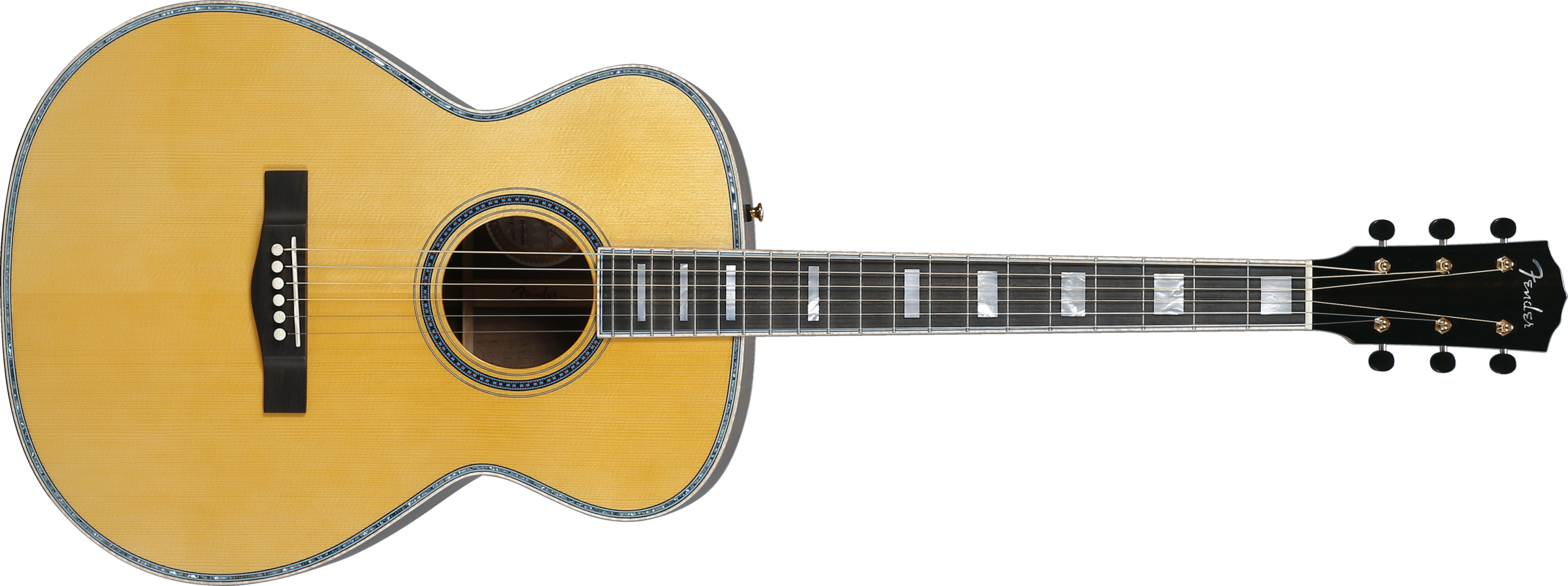
Application to other instruments
Many instruments follow a similar string-bridge-body sound producing mechanism. The guitar is another great example of such a system. Although the bridge of the guitar is a “slab” as opposed to two isolated points like a violin, we can consider the guitar bridge to be a solid slab moving in bulk. Thus, we can apply an actuator with a slab contact with the body of the guitar. This has been a research interest of A. Mamou-Mani at IRCAM, Paris, France, of whom I had the chance to converse with during a recent conference! The research project there is called “Active Instruments” which aims to combine the best of acoustic instrument design, signal processing and acoustic body diffusion.
Many traditional world instruments also feature this design, perhaps the principles of the surrogate soundboard can be applied to these instruments? For example the Northern Thai fiddle called “Salo” features a coconut body and a simple wooden bridge. What are the possibilities when cutting edge actuator techniques and physics are combined with traditional instrument-making methods!


1 Comment